Fundamentals of Gear Geometry: Modules, Pitch, and Pressure Angles
Gears are everywhere—inside the engines of cars, planes, and industrial machines. Understanding how gears work is fundamental to mastering mechanical systems. Gear geometry governs how gears transmit power and handle forces, affecting everything from durability to efficiency. In this article, we’ll dive deep into the core parameters of gear design: module, pitch, and pressure angle. Additionally, we’ll explore other critical elements such as adendum, dedendum, tip relief, root relief, and more.
What is Gear Geometry
Gear geometry refers to the shape, size, and alignment of a gear’s teeth. These factors determine how smoothly a gear transfers power between two shafts (Learn Here More), its load-bearing capacity, and its longevity. Proper gear design ensures efficient power transmission, minimal wear and tear, and reliable performance in all mechanical systems.
The module links teeth count to pitch circle diameter. It sets gear tooth size and affects load, contact ratio, and efficiency. Choosing the right module is vital for gear performance.
The pitch is the space between teeth centers. The pitch circle diameter, based on module and teeth count, is crucial for gear meshing. The two-ball measure helps understand gear geometry and design.
The pressure angle is the angle of gear tooth engagement. It impacts load, efficiency, and noise. The operating pressure angle is especially important for smooth gear operation.
| Gear Geometry Parameter | Description | Significance |
|---|---|---|
| Module | Relationship between the number of teeth and pitch circle diameter | Influences load-bearing capacity, contact ratio, and gear efficiency |
| Pitch | Distance between the centers of adjacent teeth | Affects gear engagement and meshing |
| Pressure Angle | Angle at which gear teeth engage with each other | Impacts load-bearing capacity, efficiency, and noise characteristics |
Key Parameters in Gear Geometry
Let’s explore the primary parameters that define gear geometry and influence how gears work in various applications.
A) Module
The dimensional parameter for a module is the magnitude describing the size of the tooth of the gear. The size of the module is provided by the ratio of the PCD to the number of teeth on the gear geometry.
Module = Pitch Circle Diameter (PCD) / Number of Teeth
The module affects:
- Tooth size: Larger modules mean bigger teeth, which can carry more load but may increase noise and require more space.
- Gear mesh: A proper module ensures gears mesh without slippage and transmit power efficiently.
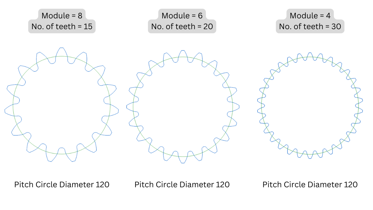
Practical Example: If a gear has a pitch circle diameter of 120 mm and 20 teeth, the module would be:
Module = 120 / 20 = 6 mm
This means each gear geometry tooth has a size corresponding to a 6 mm module, which dictates how it meshes with other gears. For more understanding refer below comparison while we keep the Pitch circle Diameter constant and changes the module.
| Gear Modules | Gear Sizing | Gear Design |
|---|---|---|
| Modules define the size and proportions of gear teeth | Gear module calculations determine the overall gear dimensions | Proper module selection is critical for effective gear system design |

B) Pitch and Pitch Circle Diameter
Pitch It is the distance between two adjacent teeth of the same wheel. The pitch is essential for the proper meshing of gears; an uneven pitch might cause incorrect gear engagement that may eventually lead to inefficiency and failure of the gear.
Pitch Circle Diameter is the diameter of an imaginary circle that passes through the points where the teeth of a gear mesh with another gear. This is one of the most important parameters in gear geometry, as the diameter indicates an influence on the speed of the gear, load distribution, and accuracy of meshing.
Refer above picture illustrating the pitch circle diameter.
C) Pressure Angle
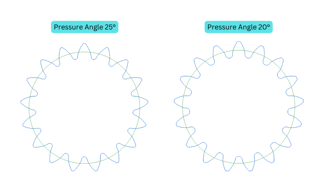
The pressure angle is the angle at which the gear geometry teeth interact when meshing. It is typically 20° or 25° in most industrial gears, each offering specific advantages:
- Higher pressure angles (25°): They provide stronger, more durable teeth but may result in increased friction and wear.
- Lower pressure angles (20°): These distribute the load more evenly but may be more prone to bending under high loads.
The operating pressure angle significantly impacts the efficiency and smoothness of power transmission. A well-chosen pressure angle can improve gear performance, while a poorly selected one could lead to premature gear failure. Below image illustrates the how changing the pressure angle affects the tooth profile.
Operating Pressure Angle:
The operating pressure angle, or pressure angle, is the angle between the line of action and the common tangent to the pitch circles. This angle is vital in gear design parameters. It impacts the load-bearing capacity, contact stress, and how the gear teeth behave during use.
The operating pressure angle is affected by several factors. These include the gear pressure angles, the gear ratio, and the tooth profile. By choosing the right pressure angle, designers can enhance gear performance and prevent failure. This ensures a smooth and efficient power transmission system.
- A higher pressure angle means the gear teeth are more undercut. This increases bending strength but might lead to higher contact stresses.
- Lower pressure angles spread the load more evenly across the tooth surface. However, the gear teeth may be more prone to undercutting and bending fatigue.
Finding the best operating pressure angle is crucial in gear design parameters. It requires careful thought about the application needs, load conditions, and desired performance.
“The pressure angle is a critical parameter that defines the angle at which the teeth of a gear mesh with each other, affecting the gear’s performance, load-bearing capacity, and overall efficiency.”

Key terms in Gear Geometry
D) Addendum and Dedendum
- Addendum: This is the distance between the pitch circle and the top of a gear tooth.
- Dedendum: This is the distance from the pitch circle to the root of the gear tooth.
These two gear geometry parameters define the height of the gear tooth and ensure that gears mesh correctly without excessive friction or clearance.
Example: In a spur gear with a PCD of 100 mm and a module of 5 mm:
- Addendum would be 5 mm (equal to the module).
- Dedendum would typically be slightly more, around 6 mm, to ensure proper clearance.

E) Tip Circle Diameter and Root Circle Diameter
- Tip Circle Diameter The tip circle diameter is defined as the diameter at the outermost point of gear teeth.
- The diameter at the bottom of the gear teeth, near the root, is known as Root Circle Diameter.
These diameters affect the overall size of the gear geometry and determine how gears will mate and transfer power. In particular, the Root Circle Diameter is very sensitive because it directly affects the strength of the gear and its resistance to stress.
Refer above image for better understanding.
F) Helix Angle (for Helical Gears)
The Helix Angle is the angle between the gear teeth, and the axis of rotation for helical gears. Since helical gears are often used because they operate more smoothly and quietly than spur gears, a higher helix angle means greater axial thrust which the supporting bearings must handle.
Example: A 30° helix angle will result in more axial thrust than a 15° angle, though the 30° angle offers smoother power transmission.
G) Tip and Root Relief
- Tip Relief: A small modification at the top of the tooth that helps prevent interference between meshing gears. This reduces vibration, noise, and wear.
- Root Relief: Provides additional clearance at the base of the tooth, preventing jamming and ensuring smoother gear rotation.
Both of these modifications extend the life of gears and help achieve quieter, more efficient operation.
Gear Design Features that Enhance Performance
Chamfering and Protuberance
- Gear Chamfer:
The gear tip chamfer is a small, angled edge at the top of the tooth. It might seem small, but it makes a big difference:
- It spreads out the load, reducing the chance of damage.
- It makes the gear’s surface last longer by reducing stress points.
- It helps oil flow better, keeping the gear running smoothly.
Knowing about these gear design features helps engineers make gears better. They can improve gears for many uses, from cars to big machines.
- Gear Protuberance: Gear protuberance means adding extra to the gear tooth shape. It does a few key things,
- It helps carry more load evenly, making the gear last longer.
- It makes the gear run smoother and quieter by increasing contact ratio.
- It strengthens the tooth root, making it less likely to break.
Chamfering and protuberance are critical features in gear design, as they improve durability and reduce the chances of gear failure, especially under heavy loads.
Clearances in Gear Geometry
Tip and Root Clearances
Tip Clearance: The clearance between the tip of one gear tooth and the root of mating gear tooth. Enough clearance prevents interference and minimizes risks of over-wear.
Root Clearance: The clearance between the root of one tooth and the tip of the mating tooth. Proper root clearance ensures no contact might lead to jamming.
Both clearances are required to be taken into account for manufacturing tolerance and thermal expansion when in service.
Tooth Form and Active Profiles
Start and End of Active Profile
The actual contacting portion with the mating gear, during meshing, is termed the active profile of the tooth. The two very significant points that indicate how the load is carried throughout its rotation by the gear tooth are the start and end.
If the active profile is not suitably designed, then it may lead to inefficient power transmission and higher wear.
Additional Information
Two Ball Measure
The two-ball method is a common way to measure gear tooth thickness. It involves measuring the space between two balls in gear teeth gaps. This method gives us the tooth thickness, a key design factor. It ensures gears fit right, engage well, and handle loads evenly.
Understanding gear pitch, pitch circle diameter, and two-ball measurement is crucial. These factors greatly affect a gear system’s performance. They influence power transmission, load handling, and smooth operation.
Tooth Thickness and Its Impact
Gear tooth thickness is key in gear design. It affects how much load a gear can handle, its wear resistance, and performance. Knowing how tooth thickness impacts gears is crucial for better performance and reliability.
Sliding Velocity:
Gears meshing together means their teeth slide against each other. This sliding can cause wear and fatigue over time. The speed at which these teeth slide, or sliding velocity, is influenced by tooth thickness. Thinner teeth slide faster, which can lead to quicker wear and a shorter lifespan.
Gear Reserve:
The gear reserve, or safety factor, shows how well a gear can handle unexpected loads. Tooth thickness is important here. Thicker teeth have a higher reserve, offering more protection against damaging loads. This ensures the gear’s long-term reliability.
| Gear Design Consideration | Impact of Tooth Thickness |
|---|---|
| Load-bearing Capacity | Thicker teeth can withstand higher loads without deformation or failure |
| Wear Resistance | Thicker teeth have a larger contact area, reducing surface pressure and wear |
| Gear Reserve | Thicker teeth provide a higher safety factor, protecting against overloads |
Designers can improve gear performance and reliability by focusing on tooth thickness. This ensures gears work efficiently and last longer.
Root Radius
The root radius is the curve at the teeth’s base. It’s key for stress distribution and preventing failure. Choosing the right gear root radius is crucial for durability and reliability.
| Gear Design Parameter | Description |
|---|---|
| Gear Form Diameters | The tip form diameter and root form diameter of the gear’s teeth, which are critical for proper meshing and load distribution. |
| Gear Root Radius | The curvature at the base of the gear’s teeth, which affects stress distribution and tooth strength. |
By focusing on gear form diameters, gear root radius, and other gear design parameters, designers can make systems that work well and last. These systems meet the needs of today’s engineering.


